And now we should get in more depth with our subtractive
synthesizer. I will try to explain what my colleague Than stated about the main
parts of a subtractive synthesizer and how we did them.
Sound is created by applying a voltage that continually repeats
a specific pattern at a really fast rate this repeated pattern is called an
oscillator.
Oscillators form the basics to create instruments, in order to achieve rich
tones and sounds we have to combine the patterns of those called oscillators by
using more than one oscillator. This is the fundamental process of a
subtractive synthesizer. A great deal of sounds can be created only by
combining the 4 fundamental tones known as: Sine, Saw tooth, Triangle and Pulse
(Simple Synthesizer
with the main Oscillator Patterns)
This is how a simple synthesizer look in Reaktor: Where the
NotePitch gives a number between 0 and 127 depending on the key you pressed on
your keyboard, the gate dictates for how long it keeps the signal going towards
the oscillator, the 4 main patterns stated above and a switch that helps us to
choose between the waveforms.
In order to achieve a different behaviour of the oscillators
we have to use an envelope. There are many kinds of enveloped but the most
common and widely used one is the ADSR (Attack, Decay, Sustain, Release),
despite the fact that the ADSR envelope is not capable of shaping all range of
sounds like for example a Spit Brass that goes like a spike at the beginning
falling down and then raising to its full amplitude, the ADSR is the best
envelope for our purpose.
(Envelope Added to the Synthesizer)
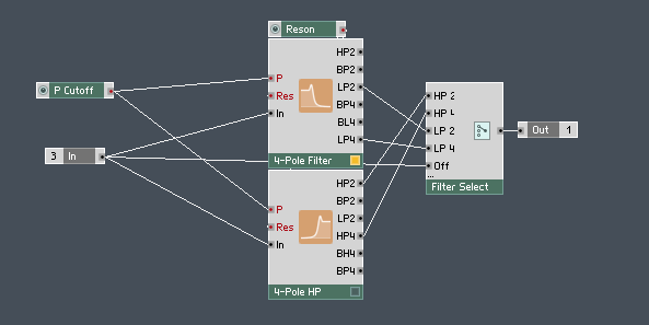
To change the sound even more we had to embed different
types of filters in our synthesizer like a Low Pass filter 2-pole and 4-Pole
and a High Pass filter also 2 and 4-pole, the reason the filters are called
2-pole and 4-pole is that for each pole we get 6dB decrease per octave so
2-pole means -12dB and 4-pole means -24dB. By adding those filters we allow the
synthesizer to get rid of some harmonics that builds the actual sound for
example a sine wave is an exception and doesn't have any harmonics but the
triangle wave contains only odd harmonics (1, 3, 5 and so on) like the square
wave but at higher frequency the triangle wave harmonics roll of much faster
and last but not least the Saw tooth wave that contains all the harmonics odd
and even.
(LP and HP filters)
This was all I knew till that moment so I started reading
some more regarding Synthesizer and especially subtractive synthesizers, by
reading their history I learned what to do next, at least theoretically, so I
started looking at today synthesizers and by analysing them I made up a scheme
with what our synthesizer should contain. Finding out from Sound on Sound and
Sound Synthesis and Sampling that many synthesizers have an actual envelope in
the filter section I started doing some research and implement the ideas
gathered in our synthesizer.
(Filter Macro)
The Gate enters once again in the envelope shaping area but
this time with a difference.
(Filter Envelope)
Because the output of the envelope varies between 0 and 1
and is an audio output, the first problem encountered was to transform the
audio signal into an event signal so I went to the Reaktor 5 help guide and I
found out that I can actually change the type of the signal. Because the cut-off
frequency of the filter has values between 20 and 120 and the envelope varies
from 0 to 1, I needed a way to increase the signal to 100 (by adding a
multiplier with a control knob between -100 to +100 we also added the
possibility to invert the envelope) the on and off switch enables the user to
activate or deactivate the filter envelope. A problem we had was when we tried
to make the filters follow the note, because the notepitch has values from 0 to
127 I was thinking to add them together and lower the value of the cut-off
frequency (between 0 and 80)then I will get the filters to follow the notepitch
but it worked only for low pass filter, for the high pass I had to built and
addition module with a constant of +40.

(NotePitch following filter)
LFO stands for Low Frequency Oscillator, is named Low
because the frequency area that uses is out of our audible range and by reading
the sound on sound article I found out that we can use LFO in many ways. LFOs
usually have the following controls: Shape which allows you to choose between
different wave shapes, rate that is usually between 0.1 and 20Hz which is the
modulation rate, LFOs have also a sync which basically is a gate input that
resets the modulation wave to zero whenever a note is played and depth which is
the amount of modulation present in the modulated sound.
LFO is usually known as modulation which creates the vibrato
effect for oscillators, where vibrato is a slight variation in pitch of a
sound.
(LFO macro)
We added the modulation effect to the oscillator and filter,
by modulating the filter and adjusting filter envelope we can make the sound of
a violin but by adding the LFO we had a problem with the note following option
on the filter so we got rid of it until we do some more research and think of an
way of doing it without affecting the note follow option or the LFO. We used a
send and receive module for the oscillator modulation by adding the notepitch
and the LFO receiver, then we made a switch for the octave shift along with
tune and fine tune. The tune knob simply shifts semitone by semitone for an entire
octave and the fine tune knob shifts only half a semitone.
(Oscillator Macro)
Something we haven’t discussed about is the selector added
after the oscillator which is a smooth way of changing between waveforms, this
allows us to create combinations between sine and triangle, triangle and
sawtooth, sawtooth and pulse enabling us to create new hybrid sounds (this
method was used mainly in older subtractive synthesizers).
The mixer at the end is simply a gain, we added a gain
control to our oscillator macro to adjust the amplitude (for example a sine
wave has lower amplitude that a sawtooth or a triangle wave this is due to the
fact that the sawtooth and triangle wave have harmonics)
LFOs are used for Tremolo and PWM as well. Tremolo is a
variation in amplitude of a sound.
(Tremolo Macro)
For tremolo we had to
modulate amplitude (in our case is the gate) we know that the gate has values
between 0 and 1, because our LFO is a Bi-Polar part like the oscillators ( goes
from negative to positive in our case from -1 to 1) we had to make it go only
positive. To make the LFO run only one way we simply multiply by 0.5 to make it
go from -0.5 to 0.5 then add 0.5 we can do this in two ways one by using the
x*y+z module which is a bit confusing or by using a multiplying module and then
an addition module so this is what we have done in the picture above we multiplied
the gate by FLO and send the signal to the oscillators of course with an On/Off
switch.
PWM stands for Pulse Width Modulation which is a fancy way
of saying that we used another LFO to modulate the Pulse Width (I should have said
earlier that Pulse and Square wave are the same thing).
(Pulse Width Modulation
Macro)
A smart thing we did
was to send the value of the knob to the PWM macro this allowed us to have an
On/Off button in the PWM control panel, we did that by using another send and
receive module.
We also tried to use an LFO to modulate the Hybrid control
of the oscillator but we didn’t like the sound of it.
(Oscillator Macro with the PWM and Tremolo)
In the top left we can see that we added a selector before
the On/Off switch for the LFO with two LFO inputs, what we had done is coping
the LFO macro once again and we added a selector to combine the two LFOs
together, we did the same thing for the filter.
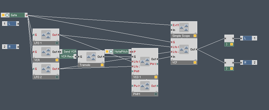
We really made use of the macros otherwise we couldn’t
explain the process because the screen would have been messy and tangled, what
we had done was tiding our work out in order to make use of the space and be
organized.
(Inside the
Synthesizer)
Something we didn’t talk about is the Simple Scope macro
that we used during the building of the synthesizer to check how the components
we have built change the waveforms and affect the sound.
(The Synthesizer Interface)
Those are the Synthesizers we analyzed till know (I mean
analyzing by looking at their interfaces and try figuring out how they are build)
(Pulverisateur
Synthesizer)
(ES 1 from Logic)
(Minimosta)